Miata Knock Sensor Upgrade
Installation of Knock sensor
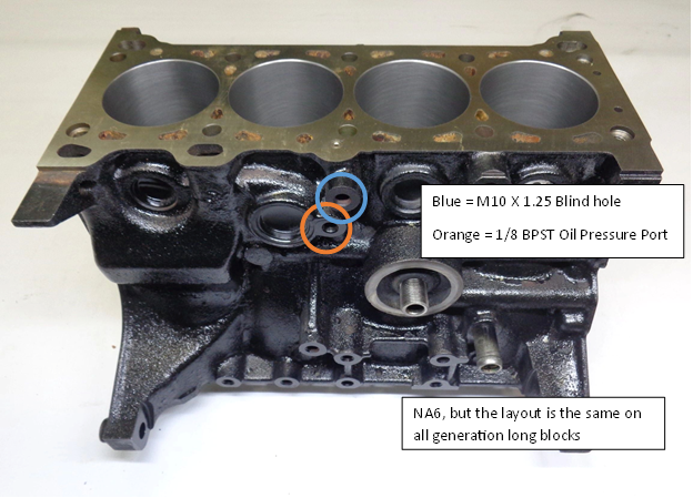
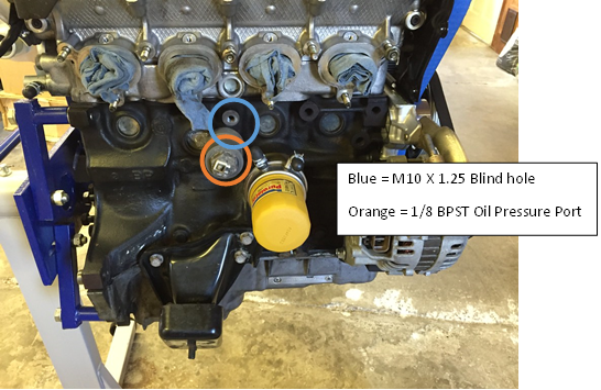
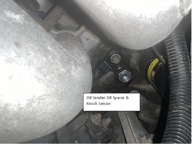
For NA6 & NA8 there is a M10x1.25 threaded blind hole that should be utilized for a knock sensor located above the Factory Oil Pressure sending unit below the intake manifold. You can access this with the intake manifold installed.
There are two steps required to install a Bosch KS4-P sensor onto a 90-97 Miata block.
-
Create clearance for the Knock Sensor
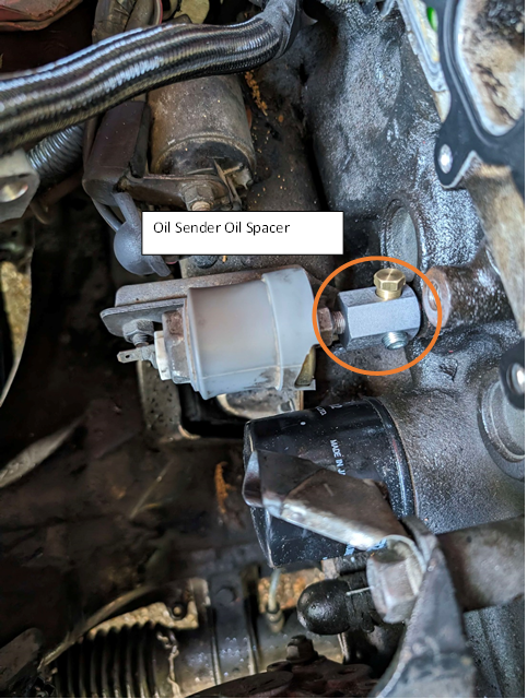
- Utilizing the factory Mazda oil pressure sender unit
- Install a 1/8 BPST spacer (male to female)
- Relocate using Oil sender remote mount kit
- Replace OEM sender unit with a Pressure Transducer
- Adapt from 1/8 BPST to Required fitting type (make sure to account for the spacing of the knock sensor)
- Utilizing the factory Mazda oil pressure sender unit
-
Mounting the knock sensor to the block and torquing it to 20nm.
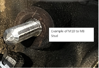
- Given the engine's M10x1.25 specs, options include employing a M10x1.25 threadsert with a M8 X 1.25 Internal Thread, crafting a custom M10x1.25 to M8x1.25 threaded stud, or using a m8x1.25 Allen Bolt and using a Die to cut m10x1.25 threads onto the external section of the bolt head.
For NB models, a factory knock sensor is pre-installed on the block. However, replacing it with a Bosch KS4-P knock sensor can offer a broader frequency bandwidth for knock detection. To make the switch, similar steps apply, necessitating the use of a M10x1.25 threadsert with a M8 X 1.25 Internal Thread, a custom M10x1.25 to M8x1.25 threaded stud, or a M8x1.25 allen nolt with threads cut using a die onto the bolt head's external section. Once the Knock Sensor is torqued to the block, wiring it into the correct pinout on the ECU is the subsequent step.
Wiring might entail additional pins and connectors depending on the Miata's model year. Below are the pinouts for the current rev of ecu’s:
- 90-95 – 2P
- 96-97 – 1S
- NB1 – 1S
- NB2 – 4M
Overview of the Block
Tuner studio Setup
When knock occurs due to factors like advanced ignition timing or high cylinder pressures, the sensor detects these vibrations. The ECU then adjusts ignition timing to prevent further knock. This constant monitoring and adjustment help protect against damage. To set this up requires the following steps:
Summary of knock detection and protection:
- Enable the knock sensor and calculate the knock frequency using an approximation formula.
- Remove ignition timing from the ignition map, adjust other parameters to prevent pre-detonation events.
- Record a log of engine performance and knock sensor levels across full RPM range.
- Restore the tune and maps to its original configuration.
- Review log data to create a baseline curve for knock detection.
- Adjust knock retard aggression to determine the level of response.
- Set up the Max Knock Retard table to define maximum allowable ignition timing retardation.
The following steps assumes your ECU is running the latest release of FOME (2312)
-
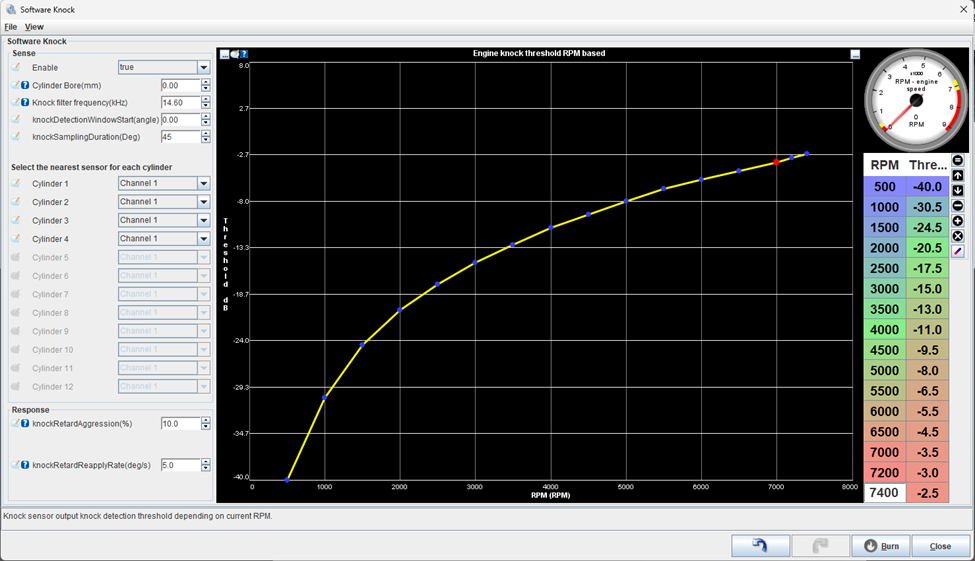
Enable the knock sensor, and calculate the estimated knock filter frequency (kHz). For now, configure the first setting “cylinder bore” as 0.00mm.
-
An adequate approximation formula for Knock Frequency is “Knock Frequency = 900,000/(π * 0.5 * cylinder bore diameter )”
-
Once the approximated knock frequency is calculated, use the second-order harmonics of the estimated frequency. The second-order frequency are multiples of the original calculated frequency. So twice the Knock Frequency. We do this to increase sensitivity, improve signal to noise ratio, and general “robustness” in frequency analysis.
-
For now, Set knock detection window start to 0.00, This feature is for advanced users only.
-
This formula is derived from the relationship between the speed of sound, the bore diameter, and the frequency of knock waves. It assumes that the speed of sound is approximately constant and that the knock waves travel at a specific angle through the combustion chamber. As an example, the NA6’s estimated knock frequency is 7300 Hz or 7.3kHz & its 2nd order harmonic would be 14.60Khz.
-
The next few steps assume your car is running well enough to take a low-load full rpm log to define the engine knock threshold curve.
An engine knock threshold curve shows how the sensitivity of knock sensors changes with engine speed. It's a graph where the horizontal axis represents engine speed (in RPM) and the vertical axis shows the knock sensor's sensitivity level (in dBV). Tuning this curve ensures the ECU reacts appropriately to protect the engine while maximizing performance.
-
Start by removing ignition timing from the ignition map, an approach is to remove 3 degrees of timing, increase octane rating, decrease boost and any other parameters that can contribute to pre-detonation events.
-
Record a log at a minimum of 100 Samples per second from idle to redline (Under Communications/Data Rate). This can be performed in a few ways. The better the Data, the better the Threshold curve:
- On Jack stands with slight load applied such as brakes
- Driving on the road in a controlled fashion
-
Restore the tune back to the previous configuration (for example, add 3 degrees of ignition timing).
-
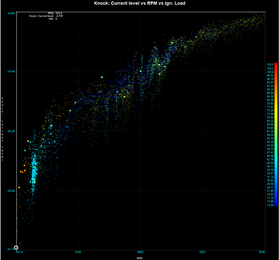
Review the log in MegaLog Viewer and generate a scatter plot of the “Knock: Current Level” vs RPM:
- Ideally the plot is the low-load noise of the engine throughout the whole rpm range. It should look something like this below.
- Further filtering can be applied in megalog viewer to remove high manifold pressure and deceleration noise. Use these expressions to help analysis the measured data.
- Deceleration : “ [RPM-4]<=[Field.RPM]&&[TPS]<50 “
- High Load : “ [Ign: Load]>60 “
- Further filtering can be applied in megalog viewer to remove high manifold pressure and deceleration noise. Use these expressions to help analysis the measured data.
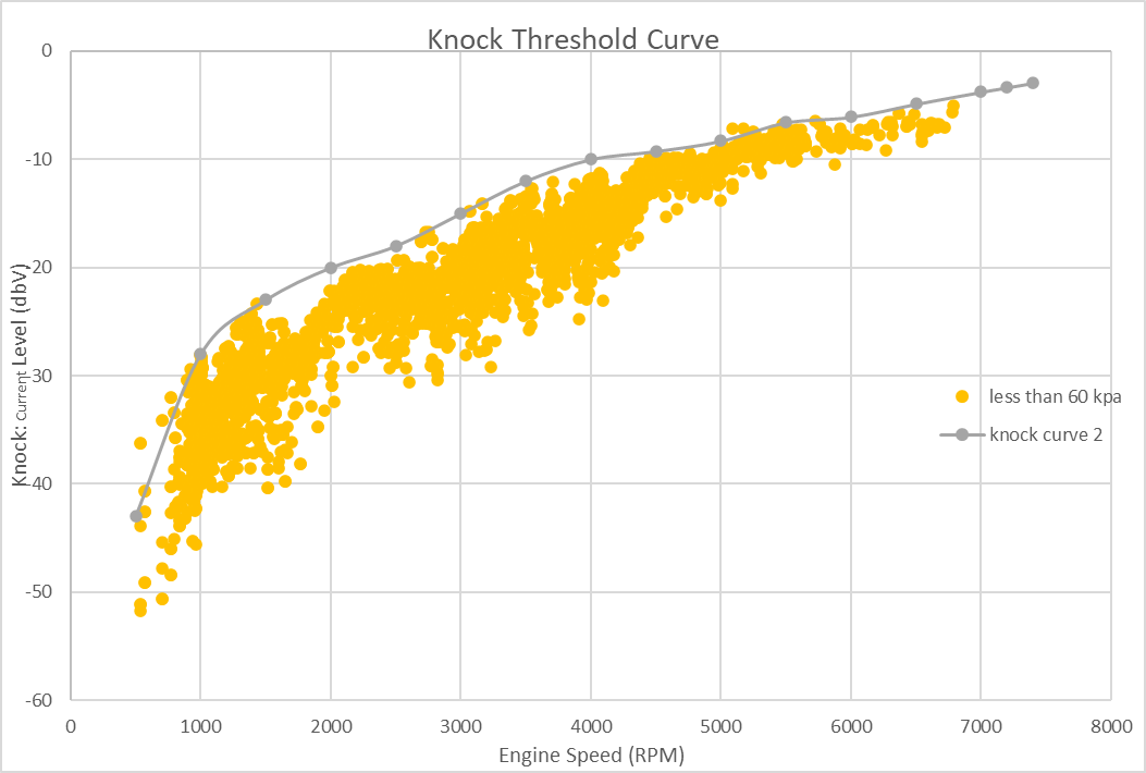
- Once the above plot for your engine has been generated, we can use this data to create a plot that will be used in Tunerstudio’s table on the bottom right. This is a baseline curve, further logs can be taken and more data reduction can used to refine the curve.
- The curve used in Tunerstudio should fit over the top of the low-load noise and also be “tight” to the measured data. As shown below, the orange scater is all the data less than 60kpa and the grey is a curve can be used as a baseline threshold in Tunerstudio.
- An active system is better than one missing low level knocks
- An active system is better than one missing low level knocks
- Ideally the plot is the low-load noise of the engine throughout the whole rpm range. It should look something like this below.
-
Set up the Response of the Knock controller’s parameter “Knock retard aggression” A generalized rule of thumb would be 5% is considered adequate where as 15% being very aggressive:
- The knock retardation amount is determined by calculating the distortion from the optimal ignition timing, multiplying it by the configured knock retard aggression percentage to determine the desired retardation, and then applying this retardation to the current knock retardation value.
-
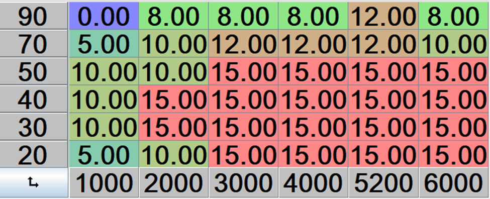
Set up the Max Knock Retard table:
- The max knock table defines the maximum allowable knock values that the knock controller can use to retard ignition timing, with the Y-axis representing ignition load, the X-axis engine speed in RPM, and the Z-axis indicating the degree of timing retardation permitted for each combination of load and speed.
- The max knock table defines the maximum allowable knock values that the knock controller can use to retard ignition timing, with the Y-axis representing ignition load, the X-axis engine speed in RPM, and the Z-axis indicating the degree of timing retardation permitted for each combination of load and speed.
Conclusion
Installing a knock sensor in a Mazda Miata involves accessing a threaded hole above the oil pressure sending unit under the intake manifold. For models NB and onwards, a factory-installed knock sensor is available, but upgrading to a Bosch KS4-P sensor broadens the frequency bandwidth for better knock detection. Installation requires creating clearance for the sensor and mounting it to the block, followed by wiring it into the correct pinout on the ECU. Once installed, the knock sensor continuously monitors knock events, allowing the ECU to adjust ignition timing and prevent damage from subsequent knock events. Setting up knock detection involves calculating the knock frequency, recording engine performance logs, and adjusting parameters such as knock retard aggression and the Max Knock Retard table to optimize engine protection and performance.
Knock Sensor Part list
| Knock | Bosch - Off the Shelf | |
|---|---|---|
| Bosch KS4-P | 0 261 231 173 | FCP Euro 2-Pin RB-Kp.1 (F02U.B00.966-01) or 0 261 231 188 Ballenger 2-Pin Jetronic (D261.205.288-01) [LK-2 Connector] |
| Bosch KS4-R | 0 261 231 218 | eBay 2-Pin RB-Kp.1 or 0 261 231 223 eBay 2-Pin RB-Kp.3 (F02U.B00.967-01) |
| Bosch KS-1-S | 0 261 231 120 | FCP Euro Amazon 2-Pin RB-Kp.1 (F02U.B00.966-01) or 2-Pin Jetronic (D261.205.288-01) [LK-2 Connector] |